
Basic principles of ac servo motor control
Composition and working mechanism of AC servo systems
An AC servo system is a closed-loop motion control system composed primarily of an AC servo motor, a servo drive (amplifier), a feedback device, and a motion controller or PLC. The servo drive receives low‑power command signals and converts them into three‑phase PWM (Pulse Width Modulation) voltages to drive the motor. Typical drive switching frequencies range from 10 kHz to 20 kHz, which allows fine current control with minimal torque ripple. The motor rotor, equipped with an encoder or resolver, returns position and speed feedback to the drive so that the internal control loop can regulate torque, speed, and position in real time, usually with a control cycle of 62.5 μs to 250 μs.
Torque, speed, and position relationships
In an AC servo motor, torque is almost proportional to current within the rated range: T ≈ Kt × I, where Kt is the torque constant (e.g., 0.7 N·m/A) and I is phase current. Speed is determined by the frequency of the applied voltage and the number of pole pairs. For example, with a 4‑pole motor and 3,000 rpm rated speed, the electrical frequency at rated speed is 100 Hz. Position is the integral of speed over time. Accurate control therefore relies on precise current control (for torque) and accurate time‑based regulation of speed and position. This layered relationship is why servo drives typically implement three nested loops: current (torque), speed, and position.
Key components in an AC servo system
AC servo motor structure and parameters
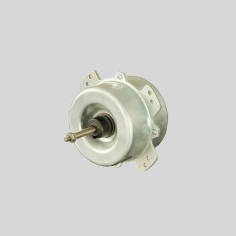
The AC servo motor itself is a permanent magnet synchronous motor (PMSM) optimized for dynamic performance. Key parameters include rated power (typically 0.1 kW to 7.5 kW in many industrial axes), rated torque, peak torque (often 2.5–3.0 times rated), rated speed (1,500–3,000 rpm), and maximum speed (commonly 4,500–6,000 rpm). Rotor inertia, expressed in kg·m², must be matched with the load inertia ratio; a drive‑to‑load inertia ratio between 1:1 and 1:5 is often recommended for stable high‑gain control. The stator windings are designed for efficient vector control, supporting field‑oriented current regulation.
Servo drive functions and interfaces
The servo drive is the core of control. It includes a rectifier stage, a DC bus (typically 300–600 VDC for 220–400 VAC input), and an inverter stage with IGBT or MOSFET modules. Functional blocks comprise current control, speed and position controllers, encoder interface, digital and analog I/O, fieldbus communication ports, and safety circuits (such as Safe Torque Off). Interfaces may include pulse/direction inputs, analog +/-10 V for speed or torque commands, and industrial buses such as EtherCAT, PROFINET, or CANopen. In wholesale and factory automation projects, selection of drive communication protocol must align with the existing PLC or motion controller platform, so supplier coordination is critical.
Control modes: position, speed, and torque
Position control mode characteristics
Position control mode is used when precise positioning is the main objective, such as in CNC axes or pick‑and‑place robots. The controller usually sends command pulses, where one pulse equals one encoder count or a defined electronic gear ratio. For example, with a 20‑bit encoder (1,048,576 counts per revolution) and an electronic gear of 1,000 pulses per revolution, 1 pulse corresponds to 0.36 degrees of shaft rotation. The servo drive closes the position loop, minimizing the position error between commanded and actual position. Typical positioning accuracy can reach ±1 encoder count, corresponding to angular accuracy better than 0.0004 revolutions.
Speed and torque control applications
Speed control mode regulates the motor speed following an analog or digital command. It is common in winding, conveying, or pumping where constant speed is critical. Speed loop bandwidths of 80–200 Hz allow rapid response to load variations, holding speed within ±0.1% even with 20–30% load step changes. Torque control mode regulates output torque based on current feedback and is favored in tension control, pressing, and tightening operations. Set torque can usually be adjusted from 0% to 150% of rated torque, with torque response times in the range of 1–5 ms. In many drives, position, speed, and torque modes can be combined or switched dynamically to accommodate complex motion profiles.
Feedback devices and closed‑loop control logic
Encoders, resolvers, and feedback resolution
Feedback devices provide the essential information for closed‑loop control. Incremental encoders output A/B/Z pulses, while absolute encoders provide multi‑turn position information with no need for homing. Modern absolute encoders often have 17–23 bits of resolution, equating to 131,072 to over 8 million counts per revolution. Resolvers offer excellent robustness against temperature and vibration but have lower effective resolution and require dedicated resolver‑to‑digital conversion in the drive. The choice of feedback is a balance between precision, environmental robustness, and cost, which becomes important in large wholesale projects involving hundreds of servo axes where component standardization reduces inventory.
Nested control loops and control cycle times
The servo drive typically runs three nested regulator loops. The innermost current loop compensates phase currents with a very fast cycle time, often 10–50 μs, using field‑oriented control (FOC) to independently regulate d‑ and q‑axis currents. The speed loop, running at 0.5–2 kHz, generates current commands based on speed error, while the position loop, running at 0.5–1 kHz, generates speed commands from position error. Stability and performance depend on appropriate loop gains and phase margins; a common design target is a phase margin of 30–60 degrees and a gain margin above 6 dB. These numerical targets ensure that the system responds quickly while maintaining low overshoot and avoiding sustained oscillations.
Setting and tuning servo drive parameters
Motor data, limits, and protection settings
Before the servo axis can operate safely, key motor and drive parameters must be set. These include motor rated current, rated speed, pole pairs, encoder resolution, and inertia data. Torque limits are typically set between 120% and 200% of rated torque, with current limits matching these values to prevent demagnetization or overheating. Speed limits should respect mechanical ratings; for a motor rated at 3,000 rpm with a maximum speed of 5,000 rpm, a safe limit of 4,500 rpm provides margin. Overvoltage, undervoltage, overtemperature, and overspeed thresholds must be configured to prevent damage, particularly in factory lines where unexpected emergency stops and power fluctuations are frequent.
Basic gain setting and response targets
Initial parameterization usually starts with auto‑tuning, where the drive injects test signals to identify load inertia and friction, then calculates recommended control gains. For many axes, a position loop bandwidth of 20–60 Hz is sufficient, with speed loop bandwidth around 100–200 Hz. These values provide a positioning settling time of 50–150 ms with overshoot below 10%. For high‑precision applications, such as semiconductor equipment, bandwidth may be pushed higher, but at the cost of lower tolerance to mechanical resonance and misalignment. A reliable supplier will not only provide drive manuals but also tuning guidelines and sample parameter sets, which are particularly valuable during commissioning of multiple axes in a large system.
PID control and gain tuning methods
Structure of servo PID controllers
The main control loops in a servo drive are generally implemented as PID or PI controllers. The current loop is usually PI (proportional‑integral) to ensure zero steady‑state error, while speed and position loops may include derivative terms or filters. In the speed loop, proportional gain determines how aggressively speed error is corrected, the integral term eliminates long‑term error, and any derivative action helps damp sudden changes. Typical proportional gains are adjusted to achieve about 5–15% overshoot on a step command, while integral time constants are set so that steady‑state error drops below 1% within a few hundred milliseconds.
Practical tuning steps and numerical checks
A practical tuning procedure starts with low gains. First, the current loop is validated by checking that commanded torque produces smooth acceleration without oscillation. Next, speed loop gain is increased until a 0–100% speed step (for example, 0 to 1,500 rpm) produces a rise time of around 50–100 ms with minimal overshoot. Finally, the position loop gain is increased while monitoring a point‑to‑point move, for example 360 degrees rotation or a 100 mm linear move, and checking that settling time remains below the required target, such as 100 ms, with position error less than 0.01 mm or 0.01 degrees. If mechanical resonance is observed, notch filters centered at measured resonance frequencies (often between 100–1,000 Hz) can be applied, with bandwidths of 10–20% of the resonance frequency.
Motion control using PLC or motion controller
Command interfaces and communication protocols
Motion commands originate from a PLC, motion controller, or industrial PC. Legacy systems often use pulse/direction outputs for position control, with pulse frequencies up to 500 kHz providing high resolution even with moderate electronic gearing. Modern systems increasingly rely on digital fieldbuses such as EtherCAT, which can synchronize multiple axes with cycle times of 250 μs or below. This allows coordinated motion profiles, such as electronic cams and interpolation across multiple servo axes. Choosing a compatible protocol is essential during wholesale procurement of drives and controllers, because mismatched communication standards can significantly increase integration cost at the factory level.
Positioning profiles and motion planning
The controller defines motion profiles in terms of acceleration, constant speed, and deceleration. A simple trapezoidal velocity profile might specify acceleration of 500 mm/s², maximum speed of 300 mm/s, and deceleration of 500 mm/s² for a 200 mm travel. More advanced S‑curve profiles limit jerk (rate of change of acceleration), which reduces vibrations, especially in high‑inertia loads. Positioning cycles must respect both motor torque and mechanical strength; if acceleration exceeds what the motor can achieve at its rated torque, either travel time must be increased or a higher‑torque motor must be used. Numerical simulation of positioning cycles helps select appropriate servo sizes before installation.
Positioning accuracy, response time, and stability
Factors affecting accuracy and repeatability
Positioning accuracy is not determined by the encoder alone. While an encoder may have a theoretical resolution of 1,000,000 counts per revolution, real‑world accuracy depends on mechanical backlash, shaft stiffness, coupling rigidity, and thermal expansion. For a ball‑screw system with 5 mm lead and 20‑bit encoder, one count corresponds to about 4.77 nm, far below practical mechanical accuracy. In practice, overall positioning accuracy of ±0.01–0.02 mm and repeatability within ±0.005 mm are realistic targets for well‑designed industrial axes. Calibration procedures, such as compensation tables, can correct systematic positioning errors caused by screw pitch variations and mounting tolerances.
Dynamic response and vibration control
Dynamic performance is typically characterized by step response, frequency response, and following error under motion profiles. A well‑tuned axis may track a sinusoidal position command at 5–10 Hz with a following error below 1% of amplitude. To achieve this, the mechanical resonance frequencies should be at least 3–5 times higher than the required bandwidth. Structural reinforcement, shorter overhangs, and stiffer couplings all contribute to higher resonance frequencies. In the drive, notch filters and low‑pass filters are used to suppress resonant peaks while preserving control bandwidth. When implementing high‑speed cycles in a factory environment, measuring vibration with simple accelerometers and adjusting filter frequencies by 10–20 Hz increments can dramatically improve stability.
Common faults, alarms, and troubleshooting ideas
Typical alarm types and root causes
Standard servo drive alarms include overcurrent, overvoltage, undervoltage, encoder errors, overspeed, and following error. Overcurrent alarms occur when instantaneous current exceeds, for example, 300% of rated current, often due to mechanical jamming or abrupt impact loads. Overvoltage usually appears when regenerative braking energy raises the DC bus above its threshold, commonly around 410 VDC for 220 VAC systems or 820 VDC for 400 VAC systems. Following error alarms arise when the position deviation exceeds a set threshold, such as 1,000 encoder counts, and may be caused by insufficient torque, overly aggressive acceleration, or wrongly tuned control gains. Effective factories maintain alarm history logs to detect repeating patterns across production lines.
Step‑by‑step diagnostic and correction methods
Troubleshooting starts with isolating whether the problem is electrical, mechanical, or parameter‑related. Measured motor phase resistance should match nameplate values within a few percent; large deviations indicate winding damage. Mechanically, axes should move freely by hand or at low jog speed without abnormal noise. Parameter checks include verifying that encoder resolution, electronic gearing, motor constants, and limits match actual hardware. Oscilloscope or drive trace tools can record current, speed, and position error during faults. For example, if position error ramps up gradually under constant load, torque limits or current capacity may be insufficient; if oscillations appear at a fixed frequency, resonance and filter adjustments are required. A technically capable supplier often provides remote diagnostic support and parameter review, which is especially valuable in large automation projects.
Installation, wiring, and daily maintenance practices
Electrical wiring standards and EMC considerations
Correct wiring is fundamental for stable servo control. Power cables and encoder or communication cables should be routed separately, with a minimum spacing of 100–150 mm, and shielded cables should be grounded at one end or according to drive recommendations to reduce noise. Protective earth connections must be low impedance, with ground resistance typically below 10 Ω in industrial installations. For long cable runs above 30–50 m, voltage drop and noise susceptibility increase, so larger conductor cross‑sections and ferrite cores may be required. In wholesale orders for factory wiring kits, standardized cable sets with pre‑terminated connectors reduce installation errors and commissioning time significantly.
Mechanical installation and periodic inspections
On the mechanical side, coaxial alignment between motor shaft and load must be checked carefully. Misalignment greater than 0.05 mm radial or 0.2 degrees angular can introduce extra bearing loads, increasing vibration and reducing service life. Flexible couplings can compensate small misalignments but must be selected based on torque rating and moment of inertia. Periodic maintenance involves cleaning cooling surfaces, checking for loosened bolts, inspecting cable jackets for wear, and reviewing alarm histories. Thermal measurements should confirm that motor surface temperature remains within rated limits, typically below 80–90°C for continuous operation. These practices extend equipment life and minimize unplanned downtime in continuous‑operation factories.
Maxtech Provide solutions
Maxtech focuses on complete AC servo system solutions for industrial users, from component selection to commissioning support. Based on torque, speed, inertia, and positioning requirements, Maxtech engineers recommend matched motors, drives, and feedback devices, including integration with PLC or motion controllers using appropriate fieldbus networks. For wholesale and factory projects involving many axes, Maxtech standardizes models and accessories to reduce inventory and simplify maintenance. Parameter templates, tuning services, and diagnostic guidance are provided so that each servo axis reaches stable operation with optimal bandwidth and minimal vibration. Through systematic planning and continuous technical support, Maxtech helps customers achieve higher productivity and stable motion performance across their production lines.
Post time: 2025-12-08 17:34:03
 Privacy settings